After a bit of research, I realized I was most certainly using the wrong revision of instructions. Whoops.
I have a Rev 4 kit, but the instructions I’ve been using are Rev 3.
Well, that also explains why I have
- four 10uF capacitors instead of six
- a few extra 1uF ceramic capacitors and
- why I have two extra resistors laying about
The good news is that I won’t have to remove or rework anything, yet I won’t know for sure until I’m done assembling and testing.
Note to self: make sure the schematics match the PCB… and vice versa.
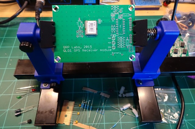
The story so far:
Still several more things to do yet:
- toroids to wind,
- a few potentiometers to install,
- jacks for headphones and an external key,
- a few pushbuttons,
- and of course a display
Will it work? No idea. But I’m eager to find out.

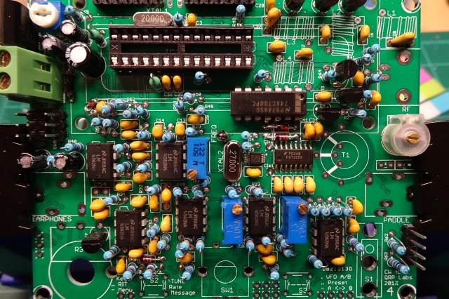
 Not quite sure what the markings are for C21, C22, and C54. The silkscreen indicates a ceramic capacitor, but the instructions call for electrolytic.